

-
×
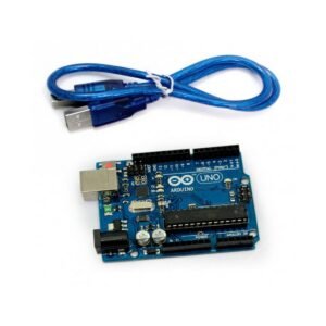 Arduino UNO R3 Dip WITH CABLE
1 × ₨ 1,579
Arduino UNO R3 Dip WITH CABLE
1 × ₨ 1,579
Subtotal: ₨ 1,579
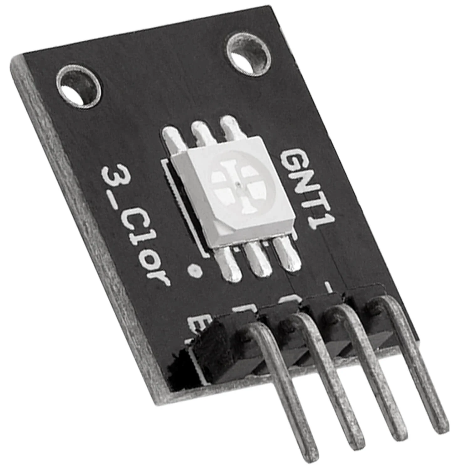


This is the SMD RGB LED Common Cathode Module, These module has 3 separate LEDs the Red, Green and Blue which can be individually driven by applying a voltage to the appropriate module pin this example code is uses the Arduino analogWrite(PWM) function to cycle through the full possible output colors this smd led module is capable of producing a rainbow color scheme.
₨ 150 ₨ 208
This is the SMD RGB LED Common Cathode Module, These module has 3 separate LEDs the Red, Green and Blue which can be individually driven by applying a voltage to the appropriate module pin this example code is uses the Arduino analogWrite(PWM) function to cycle through the full possible output colors this smd led module is capable of producing a rainbow color scheme.
There is a 4-pin header on the assembly for making connections.
1 x 4 Header
NOTE: On some modules, we have found the labeling on the R and G channels to be swapped. If you go by our connection diagram, you should be good to go.
| Maximum Ratings | ||
| Vcc | 5V | |
| IMax | Maximum Current Draw per LED | < 30mA |
| Operating Ratings | ||
| Voltage Drop | Red LED | 1.8-2.4V |
| Green LED | 2.8 – 3.6V | |
| Blue LED | 2.8 – 3.6V | |
| Polarity | Common Cathode | |
| Dimensions | L x W (PCB) | 20 x 15mm (0.75 x 0.60″) |
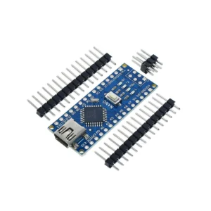
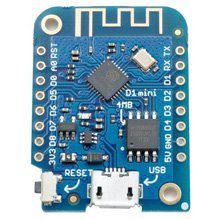
D1 mini is a breadboard which is compatible with WiFi development board on the ESP8266. It is a mini Arduino with WiFi module and has one analog port and 11 digital ports. t runs from 5V or 3.3V. Logic levels are 3.3V for all ports.

There are no reviews yet.